Handshake, an NFC business card
A business card made as a circuit board: one NFC chip and a four-turn copper coil around the edge, no battery. Tap it with a phone and this site opens.
Finished: five cards built, all five work. Updated 6 Nov 2026.
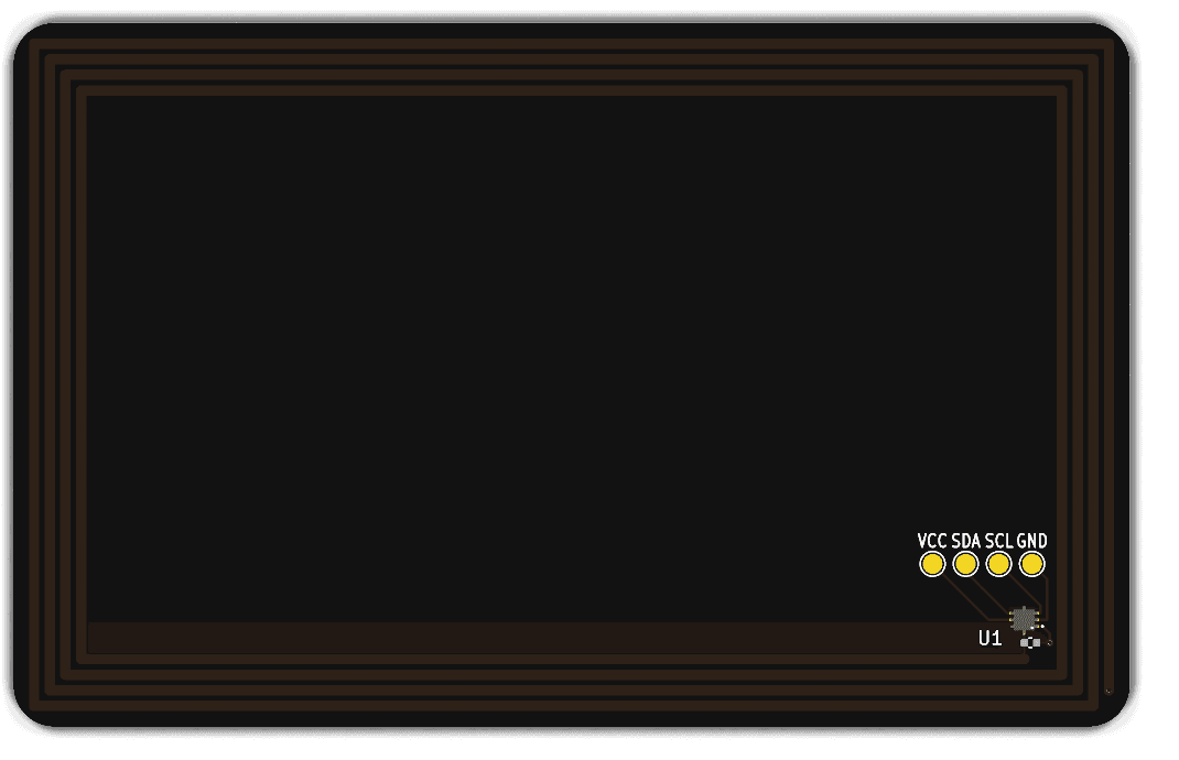
The whole card is the antenna
The coil and the chip's own 50 pF form the resonant circuit, and a phone transmits at 13.56 MHz, so the coil needs about 2.76 µH. Inductance in a flat spiral rises with the number of turns to the power 1.8: five turns give 3.74 µH and resonate near 11.7 MHz, too low to read well. Four turns of 0.8 mm track give 2.54 µH.
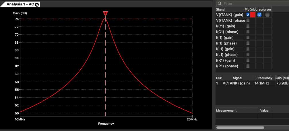
That leaves the bare card at about 14.1 MHz, high on purpose. Board capacitance and the phone's own coil pull the resonance down, and a tuning capacitor can only lower it further. A card that starts low can't be fixed without cutting copper.
Simulated in KiCad's ngspice as coil, capacitance and a 5 kΩ load, the sweep from 10 to 20 MHz peaks at 14.1 MHz, where the hand calculation put it, with a Q of about 20.
What's on the card
The chip is NXP's NT3H2111, an NFC Forum Type 2 tag in a 1.6 by 1.6 mm package that JLCPCB can place. NXP's NTAG 213 to 216 only come as inlays, the NTAG 424 DNA had no stock, and ST's ST25DV reads at a shorter range on phones. The board is 85.6 by 54 mm and 0.8 mm thick, with a black mask and ENIG. Only the two antenna pins do anything during a tap; the rest each have a job.
Coil
Four turns of 0.8 mm track, drawn as a footprint by a short Python script that checks the gap between turns and the distance to the board edge before it writes anything.
Chip
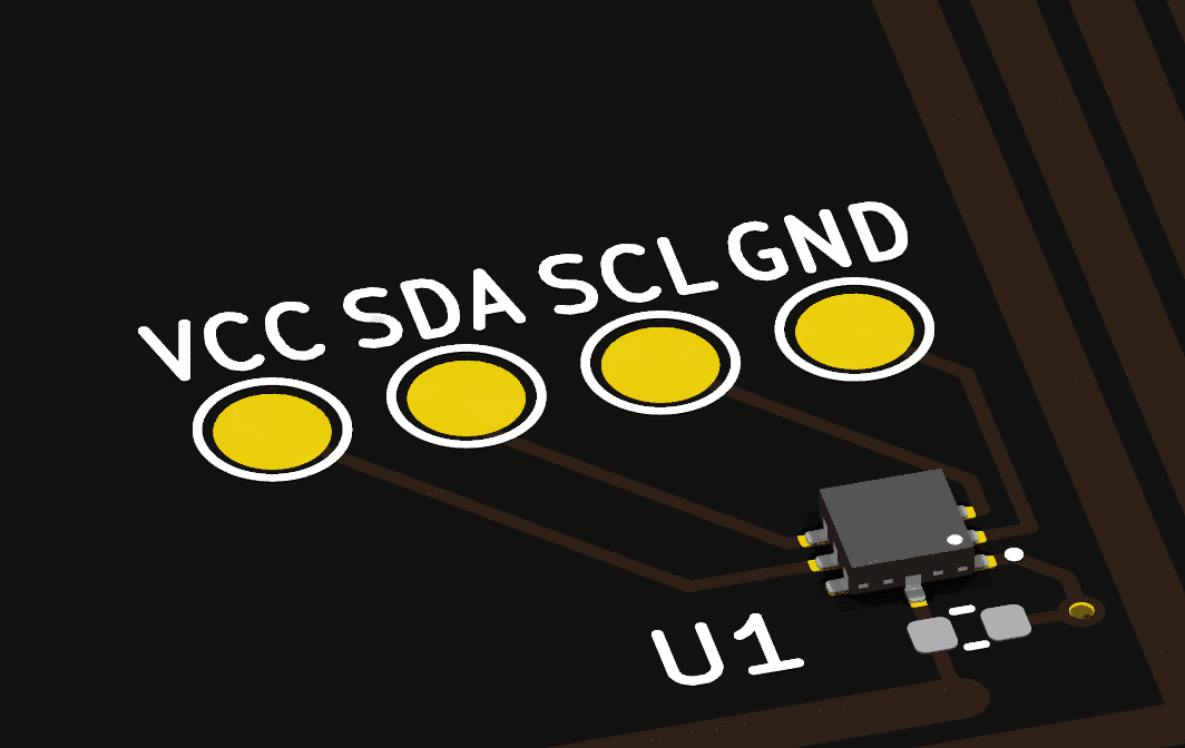
Turned so the coil's last turn ends straight under one antenna pin. The other end crosses the turns once, on the back, through two vias. The first routing pass needed six.
Tuning pads
Two empty 0402 pads across the antenna. About 4 pF would bring a 14.1 MHz card to 13.56 MHz, if a measurement ever says it needs it.
Test pads
VCC, SDA, SCL and GND on four 1.5 mm pads, so a pogo-pin jig can write the tag over I2C if a phone can't.
FD and VOUT
Left unconnected. Both serve a host microcontroller, and this card has none.
All five cards work
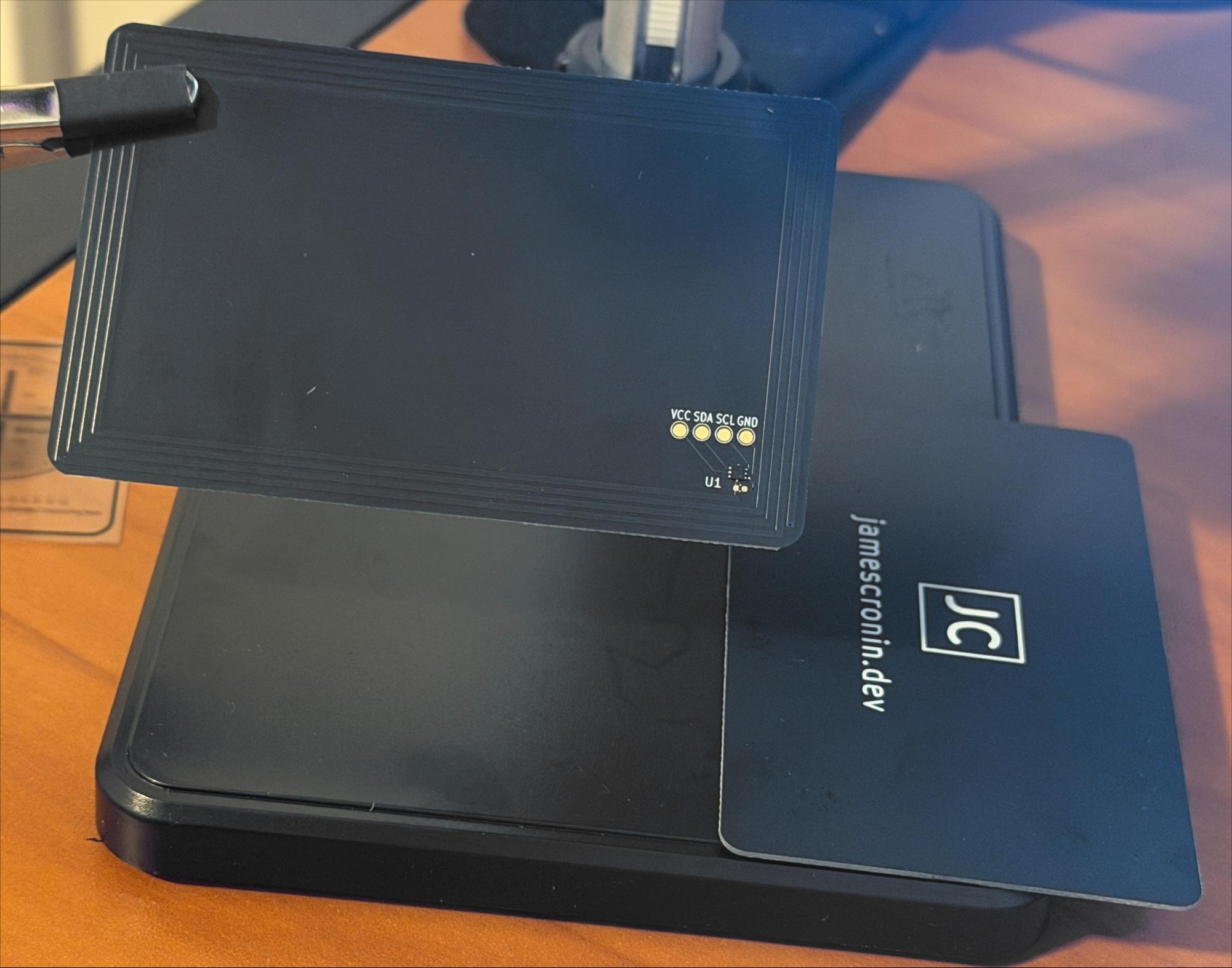
JLCPCB built five, chip placed and edge rails removed, so the cards arrived clean. Each opens this page from an iPhone, no app needed, from roughly 4 to 5 cm. The target was 1 to 3 cm, and the tuning pads stayed empty.
The first tap did nothing: every app could read the card and none could write to it. I blamed the coil. The tag's own state explained it (NDEF capable, not formatted, zero bytes), and so did section 8.3.10 of the datasheet. The Capability Container ships as all zeros; a ready-made sticker has it set, a bare chip on your own board doesn't. Two raw writes, the empty message first and the header last because those bits can't be cleared again, and every card took the link.
Left undone
- The resonance was never measured on a NanoVNA, so 14.1 MHz is still a prediction. The read range says it's close; it doesn't say how close.
- All five cards open this same page. The per-card links and the tap counter from the plan aren't built.
- The cards aren't password-protected, so their links can still be rewritten.
Build log
- Five for five, after one blank header
- Rev A ordered
- Rev A layout, ready to order
- Schematic done, and the simulation agrees with the maths
- Architecture, and why the antenna has four turns
For engineers
The architecture note covers the chip choice, the coil formula from NXP's AN11276 and the tuning plan.
Built with
 KiCad
 Python
- NXP
Plus ngspice inside KiCad, JLCPCB for fabrication and assembly, and NFC Tools and NXP TagInfo on the phone. Product names and logos are trademarks of their owners.